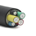
Single-core Parallel Type and Multi-core Twisted Type Cable

The advent of power cables has greatly improved the safety of power generation, transmission, transformation, supply, distribution, and use of electricity. Single-core power cables appeared first. As there are more and more occasions for three-phase four-wire power supply, three-phase five-wire power supply and multi-loop power supply in actual use, the requirements for occupied space and laying occasions are also getting higher and higher. When multiple and multi-layer laying are required, and the space occupied and laying conditions are limited, single-core power cables cannot be used conveniently. Therefore, multi-core power cables have been developed and quickly entered the field of power applications, and are accepted and used by the majority of users.

1.Busway
With the rapid growth of power cable usage, even if single-core power cables are used in actual use, the joints and branches shall be stripped and insulated on site, and the branches or joints shall be crimped before using epoxy resin insulation The method of material encapsulation treatment still has disadvantages such as large site occupation, long construction time, high cost, multiple equipment, high technical requirements, and high difficulty, especially the joints or branches after the completion of the on-site construction, and their insulation Strength, reliability, and consistency are difficult to guarantee. Therefore, the busway was developed, and after the development was put into the market, it was quickly accepted and used by a large number of users.
With the increase in user usage, it is found that the bus duct also has some defects, such as too many parts connected by * screws, complicated installation and construction, and large maintenance and high maintenance costs. In the process of operation, it often encounters the influence of electromagnetic vibration, thermal expansion and contraction, expansion coefficient, external force and other factors, which will cause the loosening of the screw. If a screw is loose, there will be heat and high temperature at the fault point, which will affect the stability of the entire bus duct. In particular, the improper use of the five-wire bus duct will also cause the contact resistance of the PE wire to increase. It violates the basic requirements for the continuity of the PE wire that is clearly stipulated in the building electrical design code and construction code. However, bus ducts still have their own advantages in the case of large capacity. Because when the current reaches thousands of amperes, if a cable is used, even a single-core cable must be laid in multiple, otherwise the corresponding large current capacity will not be reached, and the busway will show its own advantages at this time.

2. Prefabricated branch cable
With the development of technology and the increasing market demand, prefabricated branch cables have been developed and developed from single-core prefabricated branch cables to multi-core prefabricated branch cables, which also include flame-retardant, fire-resistant, and armored prefabricated branch cables. That is, in the factory, in accordance with the cable specifications, models, cross-sections and specific locations of the branches specified in the architectural design drawings, special production equipment and molds are used on the professional production line, which can be completed in one time. Its advantage lies in the high insulation strength, the encapsulated injection-molded branch joint connector and the outer insulating sheath of the cable are tightly bonded together, and it has excellent water tightness and air tightness. Because it is made of factory-specific equipment and molds, It has excellent reliability and consistency, and it is extremely convenient for users to install and use. When installing vertically, only the main cable can be evenly fastened to the corresponding bracket. In horizontal, pre-buried, overhead, tunnel, airport runway, port Construction and installation under environmental conditions such as docks, mines, and modern industrial plants are simpler and more convenient. The requirements for site, equipment, technical level of construction personnel, and costs during the installation and construction process are much lower than those for handling cable branches or cables at the construction site. Busway: It saves a lot of maintenance costs during operation and reduces the power outage time. In some cases, it can achieve the effect of maintenance-free. In the case of small cable shafts and cable channels, it can show its unique advantages. Therefore, branch cables are ideal products to replace bus ducts in medium and small capacity power supply occasions.

3. Stranded and twisted prefabricated branch cables
With the acceptance of prefabricated branch cables by the majority of users, a variety of prefabricated branch cables have entered the market under the situation of rapid increase in usage. This situation has brought a certain degree of selection to building electrical designers. difficult. The choice of stranded type, also called twisted type, branch cable is introduced below.

4. Multi-core prefabricated branch cable
The multi-core power cable is the core wire conductors are individually insulated, and are collectively and parallelly enclosed in the same outer sheath. Inside the outer sheath of the entire power cable, whether it is armored or unarmored, all power cable core wires that have been independently insulated and encapsulated are parallel and tightly encapsulated in the outer insulation. Set of interior. During the entire encapsulation process of the outer insulating sheath, no part or any power cable is allowed to “cross”, “displace”, or “twist” inside the sheath. Of course, “twisting” is not allowed. If any of the above phenomena occurs, the entire power cable will be judged as “unqualified” and not allowed to leave the factory. Therefore, the multi-core power cable itself is a qualified product that uses special production equipment in a professional production plant and strictly follows the relevant standards. Regardless of the distribution of inductance and capacitance and the basic requirement that the vector sum of any part is equal to zero, good consistency can be guaranteed. This cannot be achieved by any “stranded conductor type” or “twisted type”, and is a basic requirement that must be guaranteed on the power distribution circuit. Therefore, prefabricated multi-core branch cables made of qualified multi-core power cables can ensure that various technical parameters and basic requirements will not be destroyed, and can ensure the stability and reliability of operation. Of course, compared with single-core prefabricated branch cables, multi-core prefabricated branch cables are much more complicated and difficult regardless of the required technical level, the complexity of the manufacturing process, and the production equipment and investment.

Conclusion
In summary, the use of “twisted” or “twisted” prefabricated branch cables in the three-phase three-wire, three-phase four-wire, and three-phase five-wire power supply loops is used as the power supply loop to ensure the safety of its operation. And stability are extremely disadvantageous. The author also consulted related materials, regulations, specifications, standards such as IEC, NEC, etc., which clearly stipulated the distance between cables and cables when laying in parallel, and the correction coefficient of the current carrying capacity of cables at various distances. The author believes: This is also enough to explain the use of power cables. The series of processes from design to laying must fully consider the distribution of capacitance and inductance during operation, electromagnetic attraction, repulsion, vibration, etc.; the temperature rise during operation (capacitance And the distribution of inductance, electromagnetic attraction, repulsion, vibration, etc. are all part of the’temperature rise’) and heat dissipation environment and conditions. Therefore, only stipulating the different correction factors for the ampacity at different distances is sufficient to explain the nature and essence of the problem. What’s more, these are facts proved by theory and practice

Multi-core Cable Parallel Connection Problem

In the actual parallel use of cables, there are more single-core cables in parallel. During the actual parallel use of single-core cables, due to the influence of the laying method, the actual current carrying capacity may not meet the actual load needs, and it may appear in actual use. Overload phenomenon. In fact, when 6 cables are laid in the air and laid side by side with no gaps, the actual reflow can only reach about 60% of the theoretical carrying capacity. If the cable load is added, the theoretical selection is not carried out according to the actual installation. Correct the situation. It is very likely that the cable will be in a full-load operating state during the actual power-on process, causing the cable to generate heat during power-on operation. Therefore, in the process of parallel laying of cables, the actual current carrying capacity is not simply a relationship of “1+1=2”. It is very likely that “1+1=1.5” or even “1+1=1” will appear, causing the cable Severe heating occurred during actual operation.
Now let’s give a simple example, such as a three-phase asynchronous motor load with a capacity of 570KW and a rated current of about 1140A. Two YJV-0.6/1KV(low voltage)-1*300 cables are used for power supply in parallel, and the given value is calculated according to the theoretical design. , YJV-0.6/1KV-1*300 single cable is laid in the air, and the theoretical calculation current carrying capacity is about 750A. The theoretical parallel current carrying capacity of two cables can reach about 1500A, which can fully meet the actual needs of the equipment. We now assume that there are 32 cables that are all concentrated on a bridge, stacked side by side, stacked and laid randomly, and the two YJV-0.6/1KV-1*300 powering in parallel are also located in it. After consulting related materials, it is found that when 6 cables are stacked in the air without gaps, the actual current carrying capacity of the cable will drop to 60% of the theoretically calculated value. Then the actual current carrying capacity of the original cable is 1500×60%=900A, and the actual carrying capacity assigned to each cable is about 450A, which is nearly 300A different from the theoretically calculated carrying capacity of 750A, so that the cable will have serious overload and heat during actual use. phenomenon.

And the actual number of cables laid is far more than 6, so the actual cable reflow may be smaller than 900A. How to solve this problem, some people have proposed to connect another YJV-0.6/1KV-1*120 cable in parallel to reduce the distributed current of the other two cables. Now we theoretically assume and calculate that after the three cables are connected in parallel, the load current In the actual distribution situation, assuming that the length of 3 cables used in parallel is 1 km, the laying temperature is all calculated at 20°C. Moreover, it is assumed that the conductor resistances of two YJV-0.6/1KV-1*300 cables connected in parallel for 1 km are exactly the same. In fact, due to manufacturing process problems, it is impossible to achieve complete consistency, and there is still a slight difference in conductor resistance. In the actual calculation process, we ignore the above influence. The maximum DC resistance of copper conductor at 20℃ is 0.0601Ω/km for copper core 300mm2, 0.153Ω/km for 120 mm2, and the actual distribution of 1140A current is calculated as 120 mm2 cross-section distribution current is (0.0601*0.0601/0.153*0.0601+0.153*0.0601+ 0.0601*0.0601)=187A, the current distributed on the remaining 300 mm2 cross-section is 953A, and the actual load current flowing on each 300 mm2 cable is about 477A. ​​In this case, the actual power of the cable still has an overload phenomenon. . In this case, the actual current capacity of the cable 120 is 435*60%=261A, which still has a large margin, but the current distribution law does not distribute the current to the 120-section cable. In fact The original problem remains unresolved. And our assumption is that there are only 6 cables, which does not meet our established requirements. Imagine adding another cable with a cross-section of 300 mm2. The actual current carrying capacity distribution law is 1140*1/3=380A. Therefore, in the actual parallel cable process, the cross-section of the cable must be calculated strictly before proceeding. Use in parallel, otherwise the problem may not be solved by adding cables in time. The best case is to use cables of the same specifications and ensure the same length, so as to ensure that the current distribution is basically even. In fact, it is very difficult to re-install and rework the on-site cable after all on-site installation is completed. Therefore, the formal design, laying and installation of the cable in the early stage is very important, and the method adopted in the later stage is often only a remedial measure, and it is difficult to solve the problem fundamentally.

In addition, there are some problems in the parallel use of multi-core cables. For armored cables, the main core A, B, and C of each cable should be staggered and used in parallel. All wires of the armored multi-core cable cannot be used in parallel. The new parallel connection is used as a single-core cable on one phase. If this is done, eddy current effects will be generated in the armored steel tape of the cable, which will cause the cable to heat up and cause thermal breakdown. Although this is a very simple electrical principle, in the process of the author’s many visits to users, sometimes users still raise similar questions and practices. In the three-phase four-wire unbalanced lighting load, the wiring and distribution method of our load should ensure that the load is distributed as evenly as possible, and the three-phase current is balanced as much as possible, otherwise it may be caused by the serious imbalance of the three-phase current. Alternating induced current is generated in the shaped steel strip, which causes heating of the cable.

The parallel use of cables should also pay attention to the tightness of the lugs at the end of each line, because the load capacity of the parallel cables is generally relatively large, and the conductor resistance per kilometer is below 0. Loose wire noses and poor contact will double the conductor resistance of the line, causing uneven current distribution and even bypassing. This will cause individual cables connected in parallel to generate heat and cause malfunctions.

At the same time, it is possible that the conductor resistance of the actual circuit of the cable may not be completely the same. Therefore, the current distribution of cables of the same type and specification cannot be absolutely evenly distributed, and there may be some differences in the actual current distribution process.

Therefore, during the actual parallel use of multiple single-core cables, corrections should be made according to their actual laying conditions, otherwise it may cause heating during the parallel use of the cables and affect the normal use of the cables.