
In the field of wire drawing, the sliding water tank wire drawing machine is widely used, that is, there is a gap between the speed of the drum and the AAAC Cables, so that the wire can slip on the contact surface with the drum, resulting in sliding friction, which drives the wire to realize drawing before and after each die.
The first is the efficiency of wire drawing production. Referring to the calculation of steel wire production efficiency, the key is the utilization rate of the machine, the size of the outgoing line, and the fastest take-up speed. If the production efficiency is calculated according to the number of kilograms per hour, then the production efficiency = take-up speed * cross-sectional area of copper clad steel * density of copper clad steel * machine utilization rate. Machine utilization refers to the actual full speed running time of the machine within 24 hours. If we get the maximum and minimum utilization error under the assumption of 100% utilization through statistics, or do classified statistics, then we can get the average error, so as to determine the efficiency evaluation of wire drawing production.
The second is the mechanism of ABC Cables drawing. Referring to the sliding drawing process of composite wire, we know that the metal plastic deformation is generally realized by the movement of dislocation on the sliding surface, and the polycrystalline deformation is also carried out by the coordination of various grains. Because of the complexity and inhomogeneity of grain boundary and the inhomogeneity of original crystal particles, the plastic deformation will not be absolutely uniform in the metal, which will affect the subsequent deformation of copper-clad steel wire.
During cold deformation, the metal will produce strain hardening effect. Because the strain hardening index of the copper layer is larger than that of the steel core, the strain hardening of the copper layer is more obvious in the drawing process (as the saying goes, hardening becomes faster), that is, the increased stress required for continuous deformation is higher. Therefore, in the drawing process of copper-clad steel, the copper layer will not be damaged under greater stress, At the same time, due to the existence of strain strengthening, the deformation tends to be uniform with the increase of deformation. Through research, Korean scientific and technological workers found that the working area angle and total deformation will lead to different changes in the proportion of copper layer, which is directly related to strain strengthening. In our company’s conventional production, through analysis and statistics, it is found that the change of copper layer can be almost ignored.
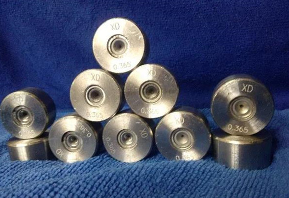
Thirdly, it is the working problem of the die. By studying the section diagram provided by the die supplier, we can know that the internal structure of the die is mainly divided into six areas: the entrance area, the lubrication area, the compression area, the sizing area, the safety angle and the exit area. The key is the yield of the compression area, the extrusion stress and the friction of the sizing area. The drawing stress is determined by the yield stress, compression ratio, working area angle, material friction coefficient and post tensile stress of copper clad steel. On the other hand, the yield stress of copper clad steel itself is also obtained by adding the yield stress of copper and steel in proportion.
Finally, through the tower wheel work on the equipment, the drawing is completed. As mentioned earlier, sliding wire drawing relies on sliding friction, that is to say, the movement speed of copper-clad steel on the tower wheel is less than the linear rotation speed of the tower wheel. In this way, it is always relaxed at the inlet end (the back tension is 0). Otherwise, if the inlet end is not tight, it will increase the back tension, thus increasing the front tension, which is easy to cause wire breakage. The final result is that the elongation coefficient of the wire through the drawing die should be greater than the gradient of the adjacent tower wheel, expressed as μ/ε> 1. In this way, during the drawing process, the wire is tightly wound on the tower wheel and moves forward synchronously, and sometimes it looses and slips. Of course, this will wear the surface of the tower wheel and increase the power loss.
The ratio of the linear speed of the tower wheel and the speed of the wire in drawing is called the sliding coefficient; The difference between the linear speed of the tower wheel and the speed of the wire during drawing is the absolute sliding amount; The ratio of the absolute sliding amount to the linear speed of the tower wheel rotation is called sliding rate; The cumulative slip coefficient is the multiplication of the slip coefficients of each pass, and the cumulative slip rate is 1-1 / cumulative slip coefficient.
The data show that the sliding coefficient is generally between 1.02-1.10. The copper-clad steel has good lubrication effect with the mold, and the relative wear with the tower wheel is also small. Therefore, some scholars suggest that the sliding coefficient should be within 1.01-1.04. We tend to 1.02.
In the actual drawing process, because each pass has preset sliding, the farther the pass is from the finished die, the greater the sliding between the tower wheel and the copper-clad steel wire, and the more serious the surface wear of the tower wheel. The uneven sliding will shorten the service life of the tower wheel. Therefore, a cumulative sliding effect should be considered, It spreads and accumulates continuously from the finished die to the incoming line. The higher the pass, the greater the slip and the more serious the wear. At the same time, the thicker the wire diameter is, the greater the drawing load is, the greater the power loss is, and the more serious the damage between the wire and the tower wheel is, which leads to the tower wheel grinding out of the groove, or the wire is thrown up to drive the mold shaking during the drawing, and the wire is not evenly stressed, Bamboo like or broken.
The tower wheel gradient (also known as tower pole ratio) of our ordinary wire drawing machine is about 10-12%. With the sliding rate, the ratio is generally set at 13-15%. According to the diameter of the outgoing line of the adjacent die, we can directly calculate the surface reduction rate or elongation, or vice versa, we know the size of a die and the required elongation, The size of the last die can be calculated. It is worth mentioning that when drawing the flexible cord, the local compression of the die must not be too large, otherwise the tension of the constant speed wheel will strain the flexible cord, resulting in the reduction of the wire diameter and the decline of the extension.
For more information on cables, click Joy ’cable Blog