
XLPE power cable has good electrical and corrosion resistance. It is easy to install and easy to operate and maintain. It is widely used in 10 kV rural distribution networks. However, once it fails, it is difficult to repair and find. Combining the actual operation and work, focus on the analysis of the principle and structure of the cross-linked cable.
1. Analysis of insulation principle of cross-linked polyethylene material (XLPE)
Polyethylene is used as the basic insulating material, and chemical and physical cross-linking methods are used to convert the high molecular compound polyethylene from a linear molecular structure to a three-dimensional network structure of cross-linked polyethylene. It completely maintains the high electrical and physical properties of polyethylene, such as: high breakdown strength, large insulation resistance, low dielectric loss tangent value, etc. At the same time, due to the cross-linking process, it has aging resistance, heat resistance, mechanical properties, The corrosion resistance has been greatly improved.
The XLPE cables used daily are mostly chemical cross-linking method-inert gas cross-linking. The polyethylene material with peroxide (commonly used dicumyl) crosslinking agent is used. After three-layer co-extrusion, it continuously and uniformly passes through a sealed crosslinking tube filled with high temperature and high pressure nitrogen. The peroxide is thermally decomposed to produce Free radicals, free radicals can combine with hydrogen atoms in polyethylene, and polyethylene molecules that have lost hydrogen atoms unite to form cross-linked polyethylene to complete the cross-linking process.
However, XLPE as a polymer also has its inherent defects. The macromolecular solid structure of the polymer makes it easy to accumulate “space charge” inside. Space charge is also called trap charge, that is, the part of the charge that stays in the medium after being trapped. , Can also refer to the polarization charge caused by uneven polarization. The formation of traps is due to pollution in the production process, introduction during mechanical processing or generated during application, but electrode injection is considered to be the main reason for the formation of space charges. The space charge is generally distributed in the medium impurities, physical defects and between polymer molecular chains. Factors such as residual charge in the production process, high electrode injection or polarization caused by impure materials will cause the accumulation of space charge, and these factors are inevitable in actual production. Space charge is very harmful to XLPE cable insulation.
In addition, due to the network molecular structure of XLPE, it has a greater water permeability problem. When the XLPE insulator invades a trace amount of moisture, it will cause the formation of water branches in the insulator, and at the same time cause a high electric field similar to the gas free process, causing insulation damage. The diameter of the water branches is generally only a few microns, and there are many microscopic small water drop gaps. composition. When voltage is applied to the cable, under the action of a strong electric field, water branches will evolve into electrical branches to induce insulation breakdown. It can be seen that the problem of water permeability is the flaw of the XLPE material, and XLPE is the main insulation, so it is necessary to strictly prevent the intrusion of the cable during installation and use.
2. Structural analysis of XLPE power cable
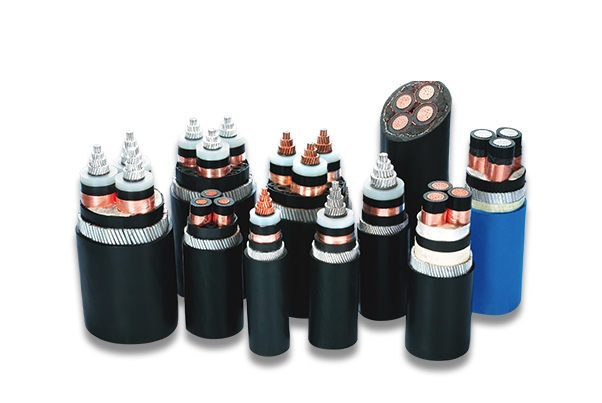
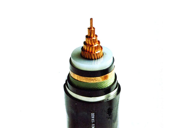
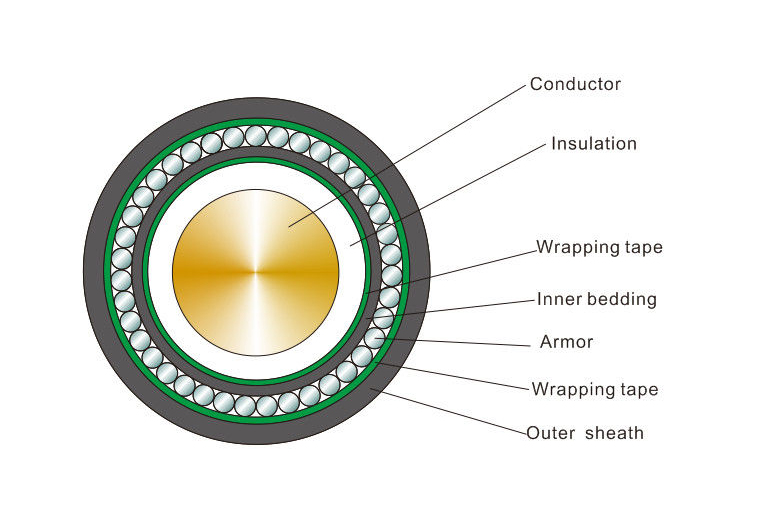
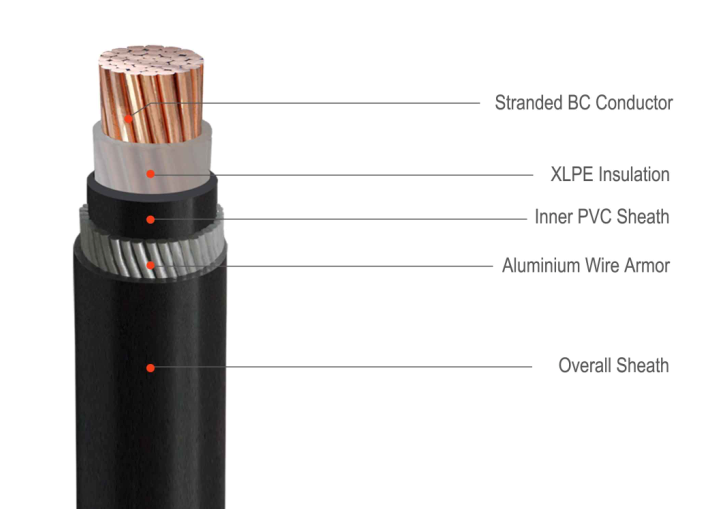
The cross-linked cable is mainly composed of a core conductor, an insulating layer and a protective layer. The core conductor is located in the center, and the insulation shielding layer of the “three-layer co-extrusion” process is on the periphery, which has excellent insulation shielding and heat resistance and heat dissipation performance. The outermost periphery is a protective layer, which is composed of an inner sheath, an armor, and an outer sheath to seal the conductor and the main insulation. This simple structure of cross-linked cable is based on high technology and craftsmanship. Each layer of the structure has special functions and requirements. If a certain layer of structure has a problem, the entire cable will be scrapped. In order to clarify The structural requirements of each layer of the cable, and the principle analysis of each structural part of the cross-linked power cable are as follows.
(1). Analysis of core conductor structure
The bare conductor of cable plays the role of transmitting electric energy. When the alternating current passes through the conductor, the skin effect makes the charge density near the surface of the conductor high. Since the electric field intensity on the surface of a conductor is directly proportional to its surface charge density and inversely proportional to the radius of curvature of the conductor surface, the radius of curvature at the edge or tip of the conductor is the smallest, the surface charge density is the largest, the space charge is most likely to accumulate, and the electric field strength is the highest. Local strong electric field discharge is most likely to occur, and this phenomenon is called “edge effect”.
If impurities invade the inner structure of the cable, the impurities will form tips and cause partial discharges, which will eventually lead to breakdown. This is another important reason why no impurities can penetrate into the cable structure.
In order to avoid the “edge effect” harm to the cable insulation, try to make the conductor electric field uniform and reduce the insulation requirements, we should make the conductor into a geometric shape with the largest radius of curvature-round, and make the conductor surface as smooth as possible to avoid The sharp electric field is strong. For this reason, the cross-linked cable core is a multi-core compact round stranded wire. It can be seen that during cable laying and installation, it is necessary to strictly avoid the behavior of damaging the flatness of the internal structure of the cable and destroying the uniform electric field.

(2). “Three-layer co-extrusion” analysis of the inner and outer semi-conductive layer and the main insulating layer
The semiconducting layer is a polymer material with a higher dielectric constant (it is a conductor under a high electric field), which makes up for the stranded cores that cannot be completely rounded, and the uneven electric field on the surface of the cores is uniform. At the same time, it can prevent manufacturing The local high electric field caused by the accidental stab of the core and the introduction of external impurities during the process. It contains substances that quickly capture moisture, which can effectively block moisture from intruding into the insulating layer from inside and outside, prevent moisture from spreading along the core, and prevent the generation of water branches. In addition, the inherent thermal resistance of the polymer can play a role in thermal shielding of separate temperature and increase the current carrying capacity of the cable.
The “three-layer co-extrusion” process is to tightly extrude the inner and outer semiconducting layers and the insulating layer, so that the three layers are tightly combined. This process avoids the local high electric field caused by the intrusion of external impurities (air, moisture, foreign particles, etc.), makes the electric field uniform and smooth, thereby increasing the initial free discharge voltage and greatly improving the insulation strength.
(3). Copper shield and armor
Between the outer semiconducting layer and the inner lining layer, two layers of annealed copper tape are spirally covered to form a cylindrical concentric conductor layer. This is the copper shielding layer, which has good contact with the shielded semiconducting layer, and For the equipotential. During installation, both ends of the copper shielding tape are grounded, so that the outer semi-conductive layer of the cable is always at zero potential, thereby ensuring that the electric field is evenly distributed in the longitudinal direction. When the cable fails, the protective device will act quickly through the ground current or short-circuit current on the copper shielding layer, thereby protecting the non-faulty part of the cable. Note that the length of the copper shielding layer not in contact with the outer semiconducting layer shall not exceed 2 cm after calculation.
The main function of armoring is to increase the longitudinal mechanical stress of the cable, reduce the influence of mechanical force on the cable, and at the same time, it also plays a role in uniform electric field and protection through fault current.
When the cable is subjected to insulation breakdown, lightning strike, operating overvoltage or large fault current flowing in the core, the induced voltage of the metal sheath may cause the inner sheath to break down and cause arcing, and the fault current at this time is not enough When the relay protection is activated, the breakdown phenomenon will gradually increase until the metal sheath is burnt into a hole, which further increases the fault. In order to eliminate this hazard, the metal sheath must be grounded at the terminal.